VMware by default comes with “vSwitch0”, the standard vSwitch which is at host level providing essential networking features such as 802.1Q VLAN tagging, egress traffic shaping, basic security, and NIC teaming required for the virtualisation setup. Then comes a vDS (vSphere Distributed Switch) which essentially operates at Data center level making configuration of multiple hosts easies to manage with added advantages like ingress/egress traffic shaping, PVLANs (Private VLANs), and network vMotion.
Nexus 1000v comes with added advantages like DHCP Snooping, IP Source Guard, Dynamic ARP Inspection, VxLAN support, Cisco TrustSec SGA support, Cisco VSG support and VN-Tagging
Nexus 1000v can be seen as another flavor of software-defined networking. The Cisco Nexus 1000V is made from 2 components VSM and VEM. The VSM provides the management and control plane functions for the Cisco Nexus 1000V Switches. The VEM provides the Cisco Nexus 1000V with network connectivity and forwarding capabilities much like a line card in a modular switching platform.
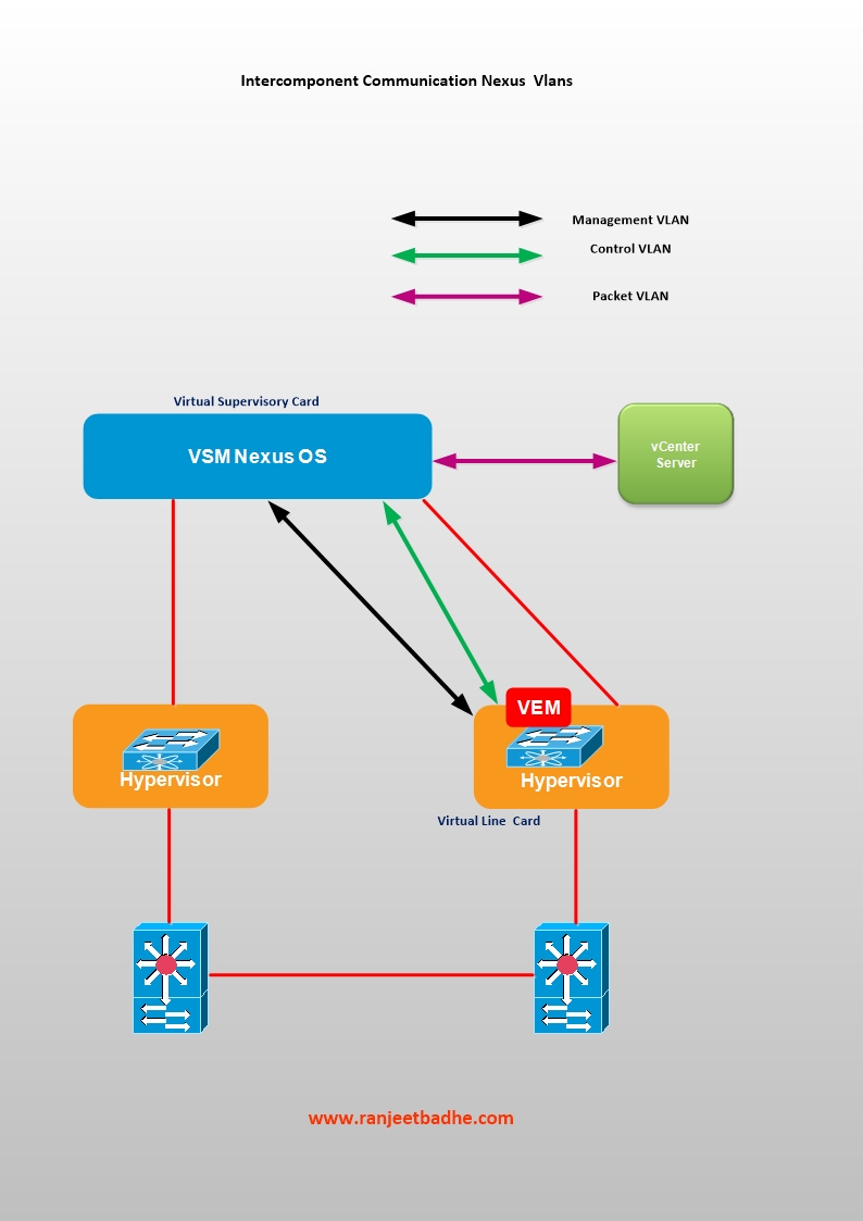 Figure 1
The Control VLAN and the Packet VLAN are used for communication between the VSM and the VEM.
Management VLAN is used by VSM Management interface to communicate with a Vcenter to publish port configuration, remote access (Management Access)
The Packet VLAN is used by protocols such as CDP, LACP, and IGMP.
This installation covers Layer 3 mode which is also the recommended mode, because of ease of troubleshooting and Packet VLAN is not needed.

Figure3
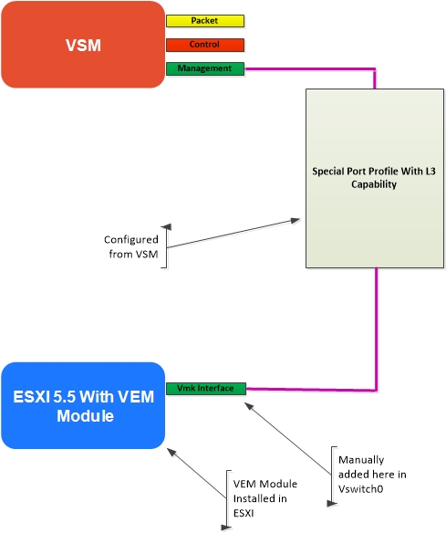
Figure4
As you will see during the installation steps we have created Kernel interface and assigned an IP address to it. The VSM to VEM communication requires a special type of port profile with the L3 capability. This has to be created from the Nexus soft switch 1000v. Ensure that you have the necessary L3 connectivity between the components and the default gateways by doing some ping pong tests. Use vmkping command to verify the VMkernel networking configuration, Ping from the VSM and the L3 routing element to all the components having L3 interface.
Let us now straight away jump to deployment of Cisco Nexus 1000v on vSphere 5.5. These steps were captured in my Home lab during the installation of Nexus 1000v .
In my lab I have 3 Dell Servers named Ganga,Yamuna and Saraswati. I also have 2 stand alone separate servers running Microsoft Active directory services/ Domain controller and the DNS. Nexus 1000v deployment needs the software like Windows 20008r2, VSphere client, ESXI5.5, Vcenter 5.5, and tools like Winscp, Putty telnet client.
The following figure depicts the logical and the physical connectivity with the following subnets and the VLAN’s.
| My Vlan | My Network Label | Subnet |
| 200 | VLAN200-N1KV_VSM_CONTROL_badhe | 192.168.200.x |
| 201 | VLAN201_N1KV_VSM_MGMT_badhe | 192.168.201.x |
| 205 | VEM | 192.168.205.x |
| 100 | VMkernel_servers | 192.168.100.X |
Table1
We are on a low budget and I have a Layer 2 Cisco Switch 2950 and with a router Cisco 2600 to perform routing between the the VLAN’s , configured in “Router on a Stick” topolgy. Alternatively you can also use virtual router to route between the VLANS used in Nexus 1000v.This setup solves the purpose of routing between VSM, Packet and the Management newtwork.
The logical diagram (Figure 1) depicts logical connections with the Vlans and the subnet assigments.The third octet in the subnet matches the vlan number and each subnet will have 192.168.x.254 as the default gateway configured on the logical interface on the router Cisco2600.
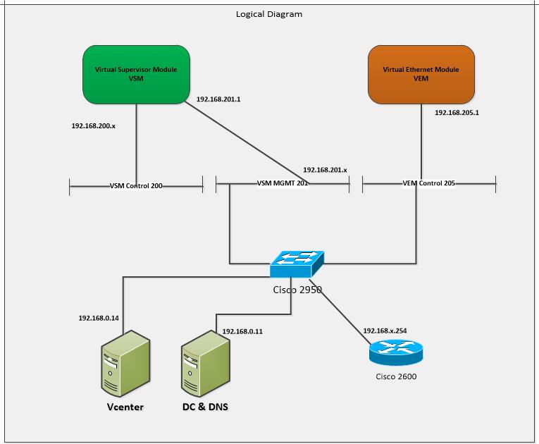
Figure5
I have installed Windows 2008R2 , Data Center version, for Domain controller (Active directory service) and DNS.All the nodes are registered in the DNS statically as shown in the figure 3
Configuration on Cisco router 2600
Here is the router configuration for inter VLAN configuration, pretty simple “router on the stick configuration”.
NEWYORK#show ip int br
Interface IP-Address OK? Method Status Protocol
FastEthernet0/0 unassigned YES NVRAM up down
FastEthernet0/1 unassigned YES NVRAM up up
FastEthernet0/1.1 192.168.0.254 YES NVRAM up up
FastEthernet0/1.100 192.168.100.254 YES manual up up
FastEthernet0/1.200 192.168.200.254 YES manual up up
FastEthernet0/1.201 192.168.201.254 YES manual up up
FastEthernet0/1.202 192.168.202.254 YES manual up up
FastEthernet0/1.203 192.168.203.254 YES manual up up
FastEthernet0/1.204 192.168.204.254 YES manual up up
FastEthernet0/1.205 192.168.205.254 YES manual up up
Loopback0 97.9.15.127 YES NVRAM up up
interface Loopback0
ip address 97.9.15.127 255.255.255.255
!
interface FastEthernet0/0
no ip address
duplex auto
speed auto
!
interface FastEthernet0/1
no ip address
duplex auto
speed auto
!
interface FastEthernet0/1.1
encapsulation dot1Q 1 native
ip address 192.168.0.254 255.255.255.0
!
interface FastEthernet0/1.100
description badhe_all_servers
encapsulation dot1Q 100
ip address 192.168.100.254 255.255.255.0
!
interface FastEthernet0/1.200
description badhe_vsm_control
encapsulation dot1Q 200
ip address 192.168.200.254 255.255.255.0
!
interface FastEthernet0/1.201
description badhe_vsm_manage
encapsulation dot1Q 201
ip address 192.168.201.254 255.255.255.0
!
interface FastEthernet0/1.202
description badhe_vmotion
encapsulation dot1Q 202
ip address 192.168.202.254 255.255.255.0
!
interface FastEthernet0/1.203
description badhe_storage
encapsulation dot1Q 203
ip address 192.168.203.254 255.255.255.0
!
interface FastEthernet0/1.204
encapsulation dot1Q 204
ip address 192.168.204.254 255.255.255.0
!
interface FastEthernet0/1.205
description Towards VMDK
encapsulation dot1Q 205
ip address 192.168.205.254 255.255.255.0
Configuration on Cisco Switch 2950
Switch#show running-config
Building configuration…
Current configuration : 2250 bytes
!
version 12.1
no service pad
service timestamps debug uptime
service timestamps log uptime
no service password-encryption
!
hostname Switch
!
!
ip subnet-zero
!
!
spanning-tree mode pvst
no spanning-tree optimize bpdu transmission
spanning-tree extend system-id
!
!
!
!
interface Port-channel5
switchport mode trunk
spanning-tree portfast trunk
spanning-tree bpdufilter enable
spanning-tree bpduguard enable
!
interface Port-channel6
switchport mode trunk
spanning-tree portfast trunk
spanning-tree bpdufilter enable
spanning-tree bpduguard enable
!
interface FastEthernet0/1
!
interface FastEthernet0/2
!
interface FastEthernet0/3
switchport mode access
!
interface FastEthernet0/4
switchport mode access
!
interface FastEthernet0/5
switchport mode trunk
channel-group 5 mode active
spanning-tree portfast trunk
spanning-tree bpdufilter enable
spanning-tree bpduguard enable
!
interface FastEthernet0/6
switchport mode trunk
channel-group 5 mode active
spanning-tree portfast trunk
spanning-tree bpdufilter enable
spanning-tree bpduguard enable
!
interface FastEthernet0/7
switchport mode trunk
channel-group 6 mode active
spanning-tree portfast trunk
spanning-tree bpdufilter enable
spanning-tree bpduguard enable
!
interface FastEthernet0/8
switchport mode trunk
channel-group 6 mode active
spanning-tree portfast trunk
spanning-tree bpdufilter enable
spanning-tree bpduguard enable
!
interface FastEthernet0/9
!
interface FastEthernet0/10
!
interface FastEthernet0/11
switchport mode trunk
!
interface FastEthernet0/12
switchport mode trunk
!
interface FastEthernet0/13
!
interface FastEthernet0/14
switchport trunk allowed vlan 1,100,200-206
switchport mode trunk
!
interface FastEthernet0/15
description “To Yamuna vmnic1”
switchport mode trunk
!
interface FastEthernet0/16
description “To Saraswati vmnic1 ”
switchport mode trunk
!
interface FastEthernet0/17
!
interface FastEthernet0/18
!
interface FastEthernet0/19
!
interface FastEthernet0/20
!
interface FastEthernet0/21
!
interface FastEthernet0/22
!
interface FastEthernet0/23
!
interface FastEthernet0/24
!
interface Vlan1
no ip address
no ip route-cache
shutdown
!
ip http server
!
line con 0
line vty 0 4
login
line vty 5 15
login
!
!
end
ESXI Server Configuration
On my ESXI host Saraswati, I have planned two virtual machines to run, the VSM as appliance and the Vcenter running on Windows server 2008r2 having hostname Vcenter2 IP address 192.168.0.14)
We will port Vswitch on host Yamuna to Nexus 1000v. We start the configuration process with the manual port group creation for test VM’s (running 64bits Windows8 Operating system) in VLAN 100 with the addition of Virtual switch vSwitch1.

Figure 3
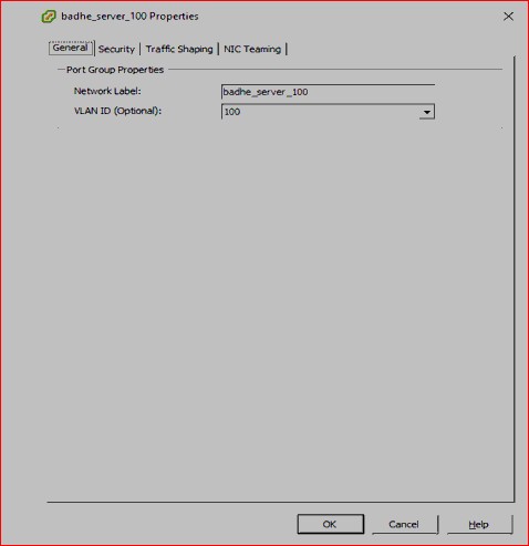
Figure4
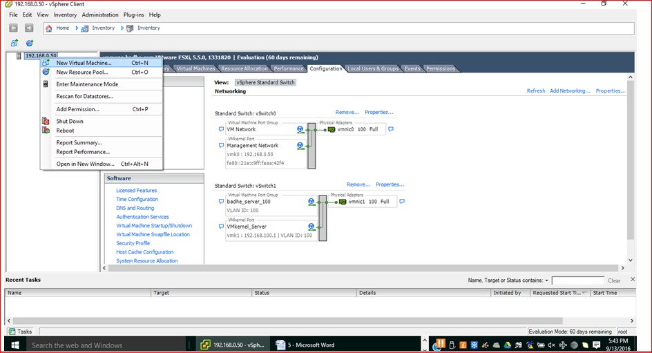
Figure 5
Figure 6

Figure 7

Figure 8
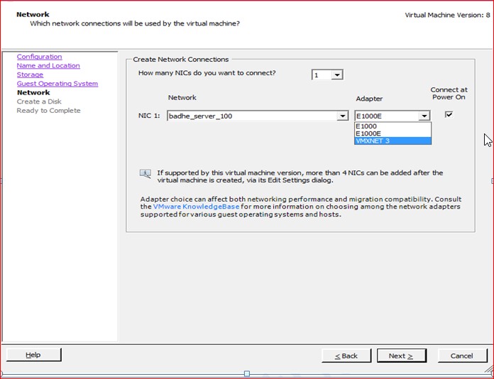
Figure9

Figure 10

Figure 11

Figure 12

Figure 13
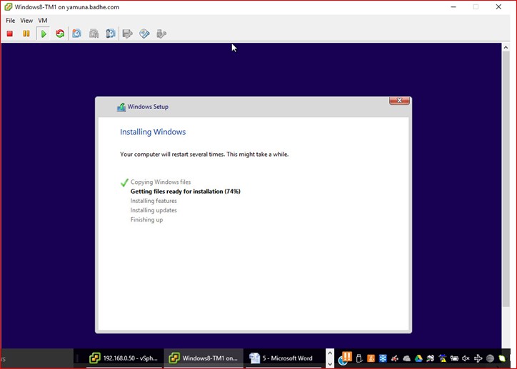
Figure 14
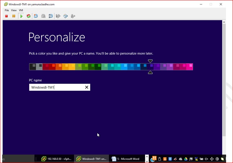
Figure 15

Figure 16

Figure 17

Figure 18
Figure 19
Figure 22

Figure 23
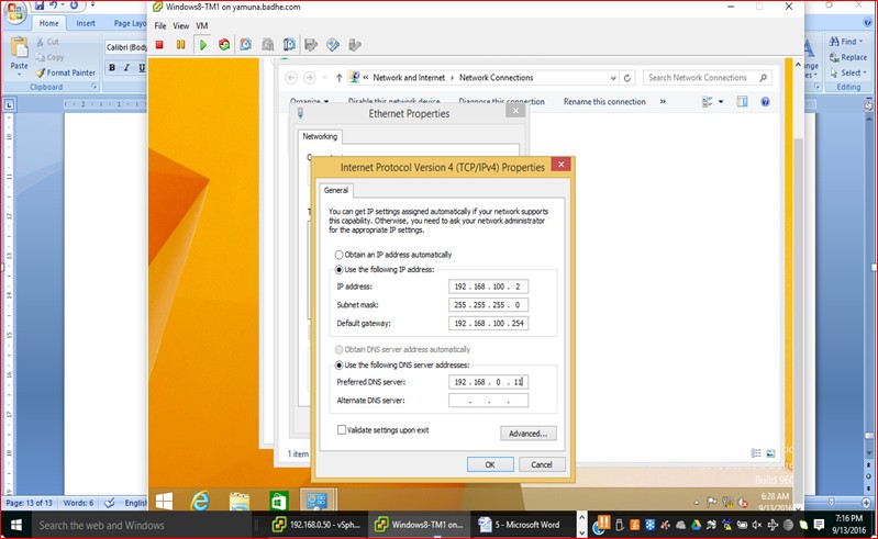
Figure 24

Figure 25
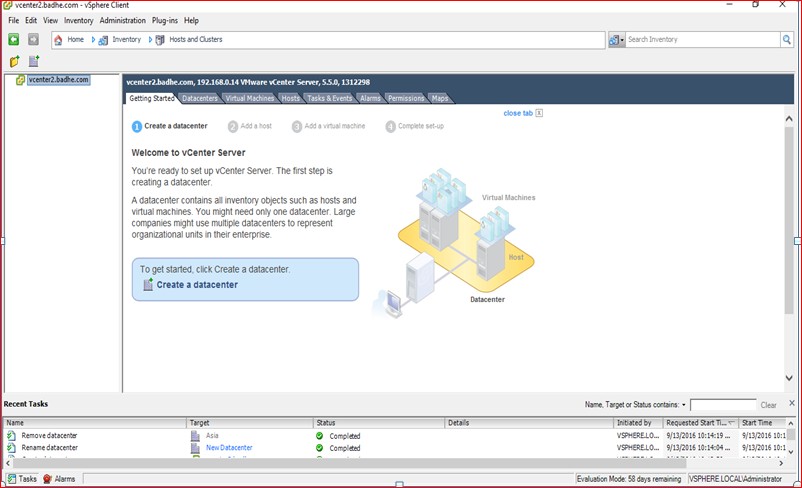
Figure 26
Figure27
Figure 28
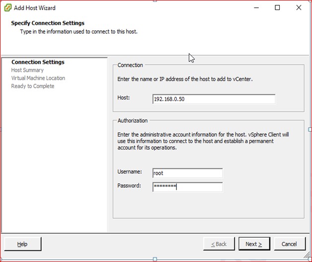
Figure 29

Figure 30

Figure 31
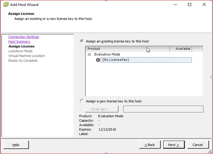
Figure 32

Figure 33
Figure 34

Figure 35
Figure 36
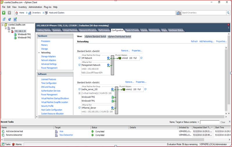
Figure 37
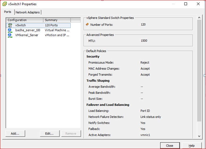
Figure 38
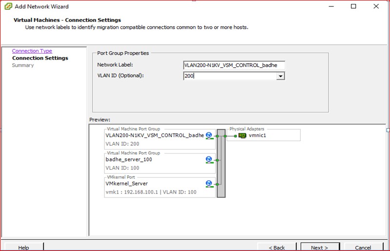
Figure 39
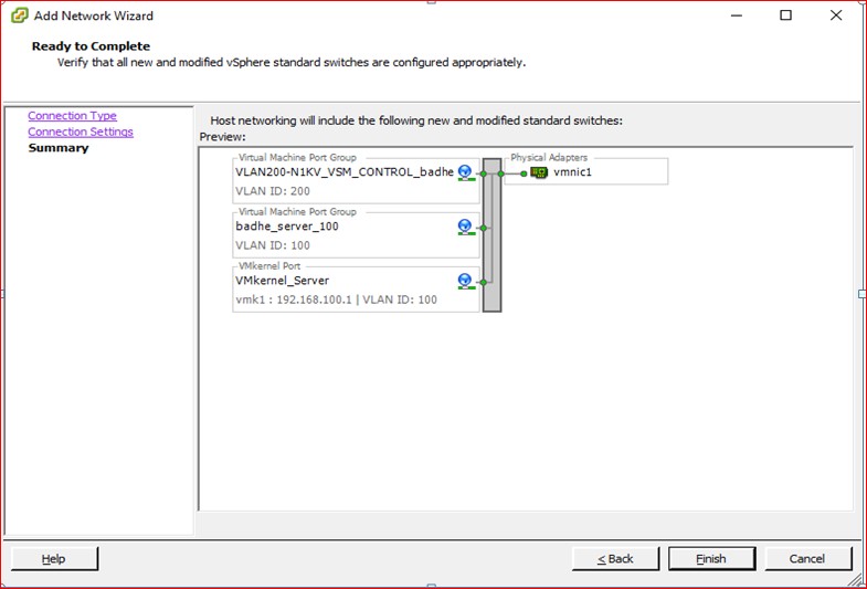
Figure 40
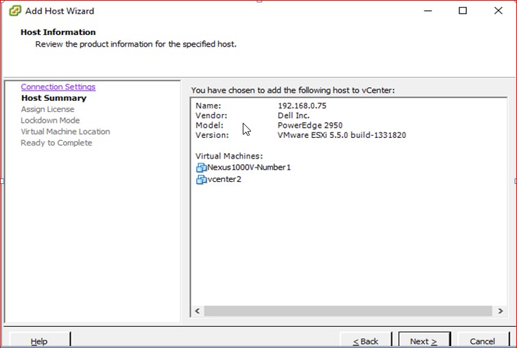
Figure 41
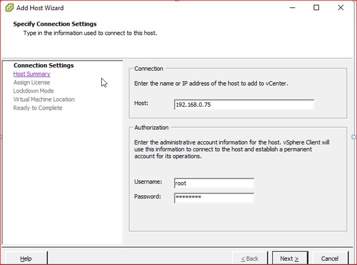
Figure 42
Figure 43

Figure 44
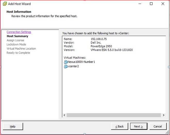
Figure 45
Figure 46

Figure 47

Figure 48
Figure 49
Adding the Nexus 1000v VM onSever Saraswati

Figure 50
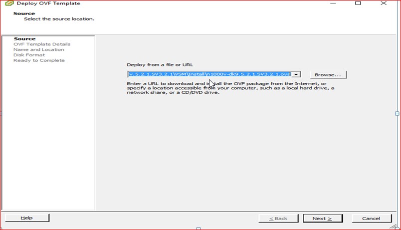
Figure 51
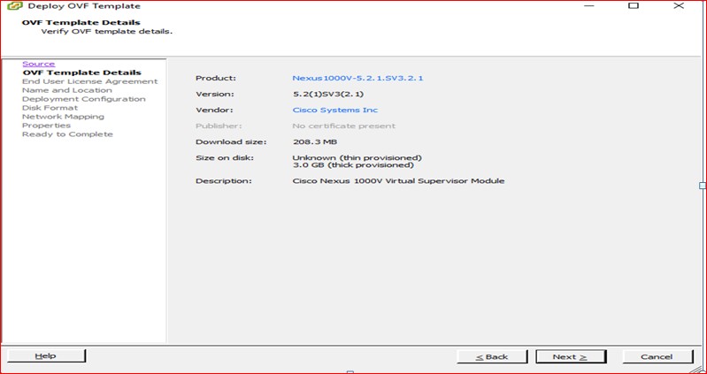
Figure 52
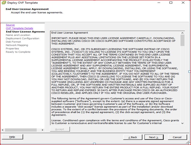
Figure 53

Figure 54
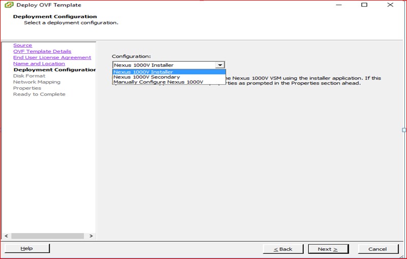
Figure 55

Figure 56
Map the VLAN’s

Figure 57
Provide the Management IP address , subnet mask and the default gateway as per the design.

Figure 58
Click next to proceed with the deployment of VSM

Figure 59
Once the VSM is deployed , the Nexus softswitch will boot .

Figure 60
Open your browser and provide the management IP address of the Nexus switch

Figure 61
Download the Plugins and the VIB files.

Figure 62
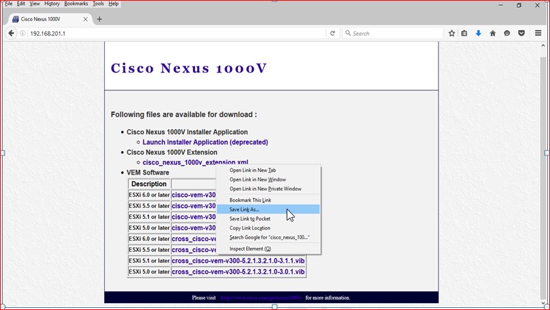
Figure 63
Now lets us install the Plugins in Vcenter . This plugin will enable communication between the Vcenter and the VSM.

Figure 64
Right click on the screen, choose “New Plugin” and provide the path where you downloaded the Plug-ins.
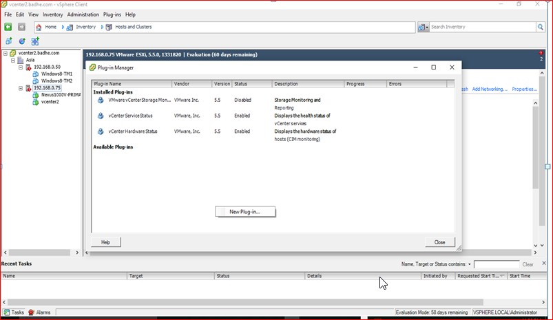
Figure 65

Figure 66
Register the Plugins

Figure 67
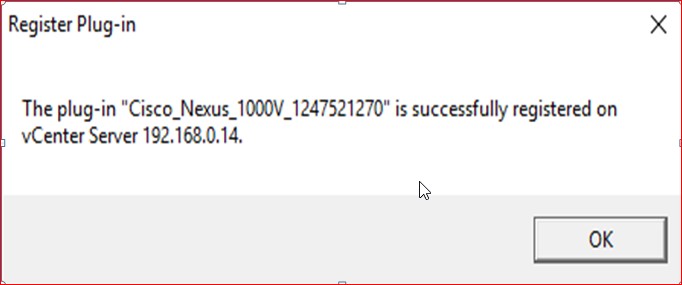
Figure 68

Figure 69

Figure 70
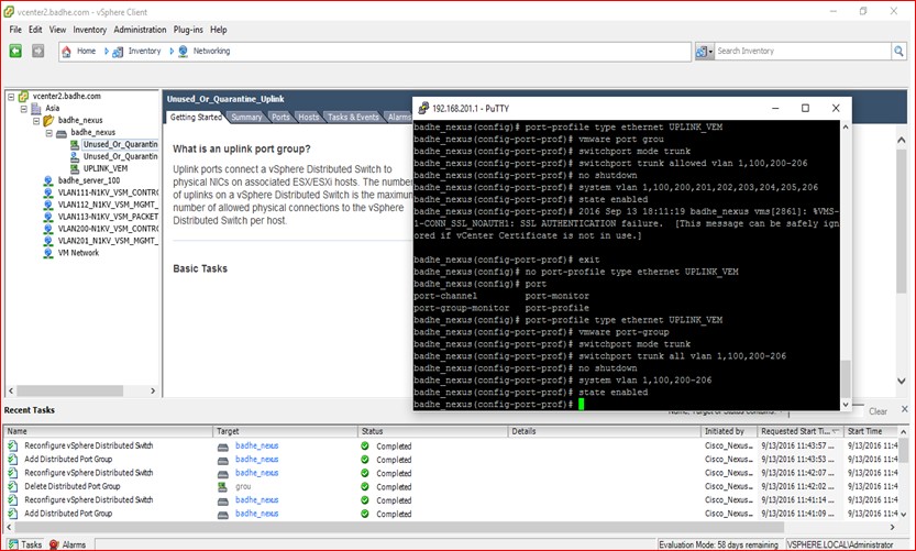
Figure 71

Figure 72
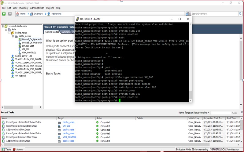
Figure 73
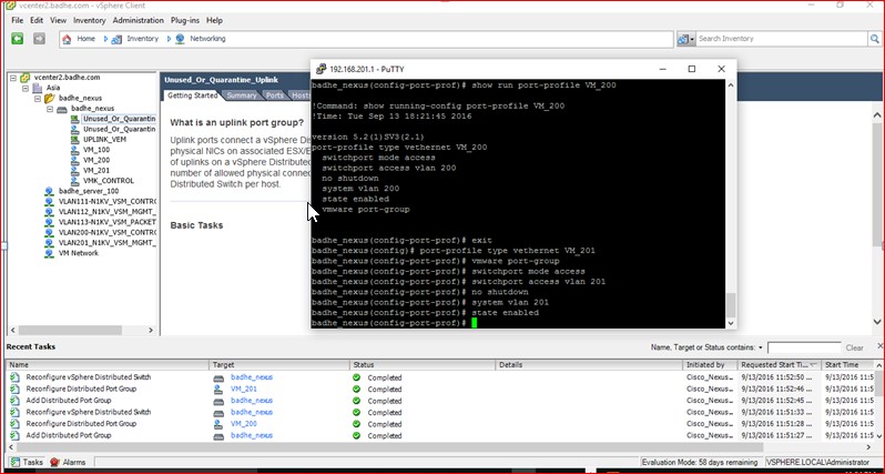
Figure 74

Figure 75

Figure 76

Figure 77
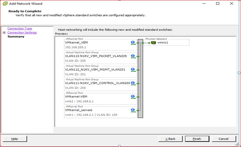
Figure 78

Figure 79
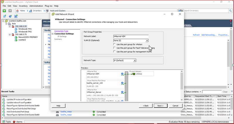
Figure 80

Figure 81
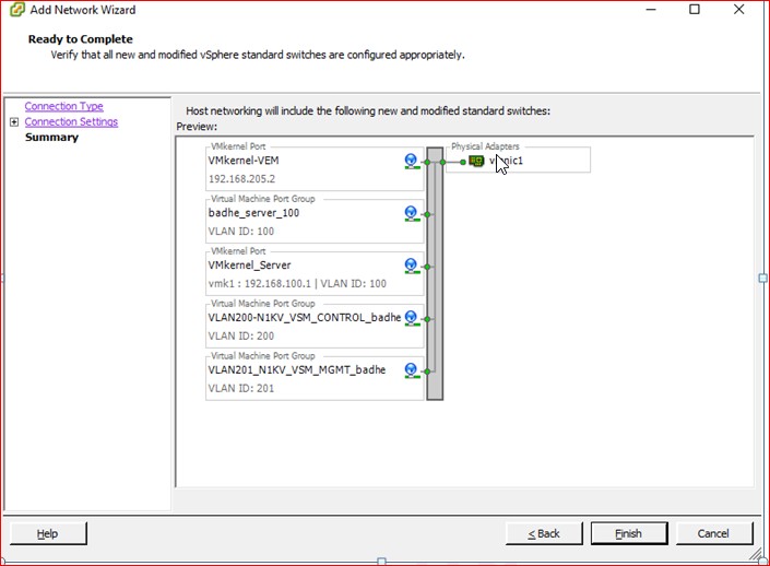
Figure 82

Figure 83

Figure 84
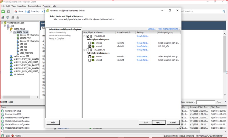
Figure 85

Figure 86

Figure 87

Figure 88

Figure 89
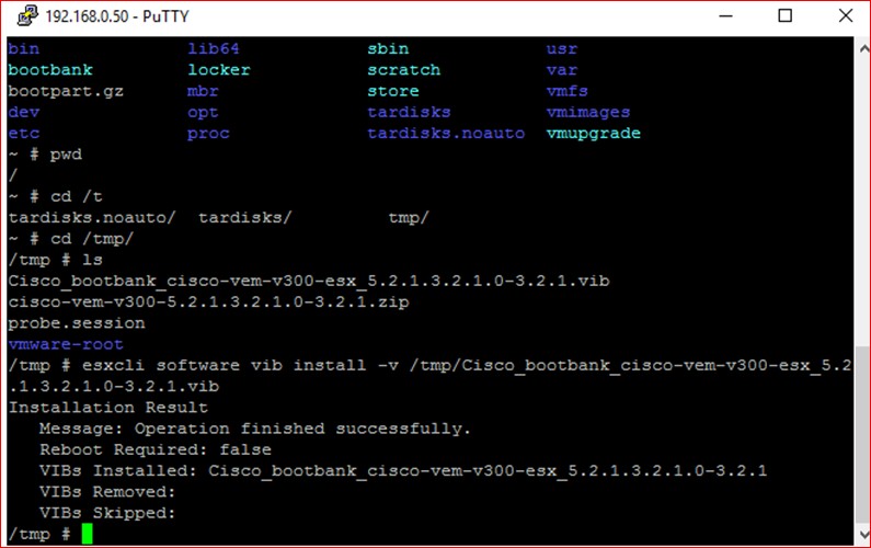
Figure 90
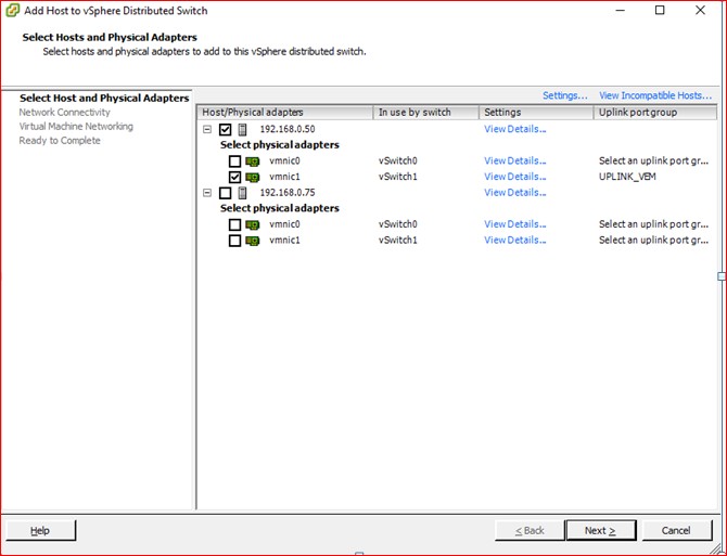
Figure91
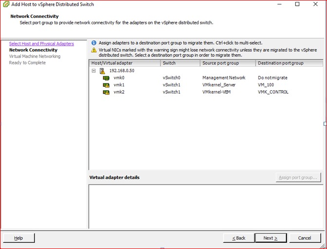
Figure 92
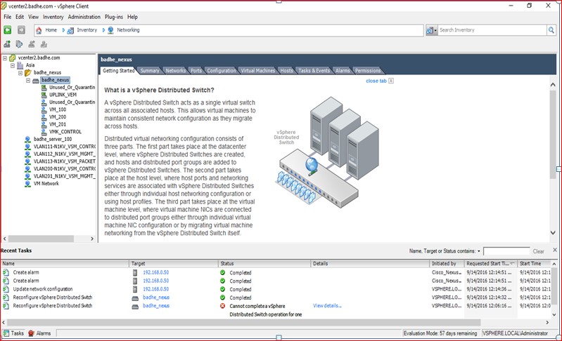
Figure 93
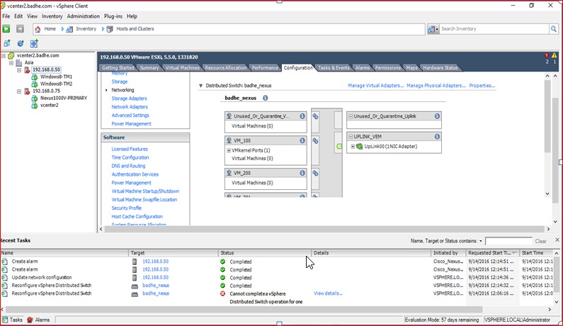
Figure 94

Figure 95
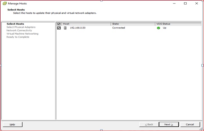
Figure 96
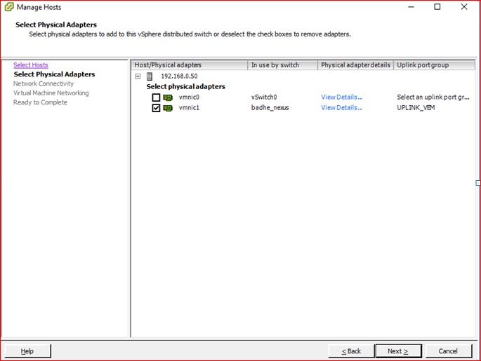
Figure 97
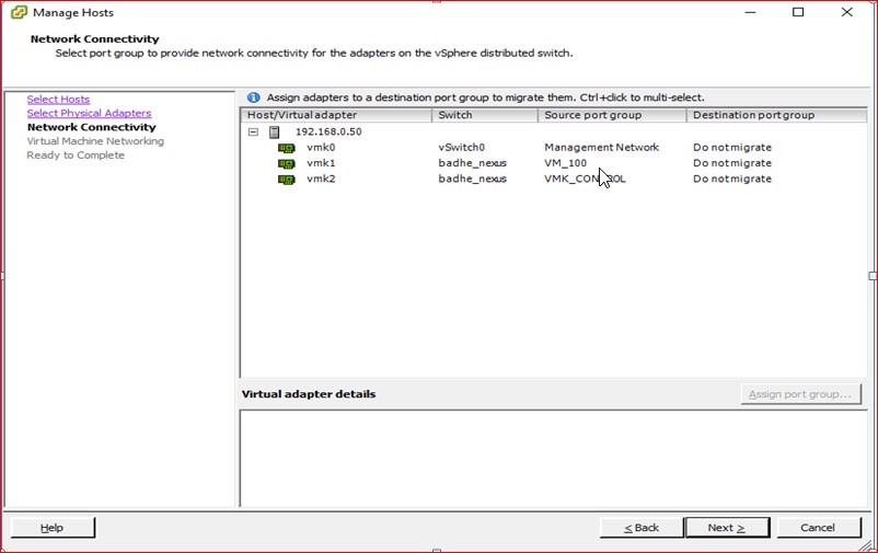
Figure 98
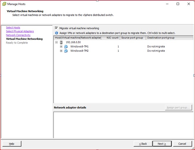
Figure 99

Figure 100

Figure 101
Figure 102