Timing is very critical in ORAN/VRAN implementations. This reminds me my stint when I used to work on Synchronous TDM (SDH and SONET), Digital loop carrier systems dealing with E1/STM/ where synchronization was THE MOST CRITICAL in transport backbone networks. As Things started moving towards packet domain and the synchronization factor became lenient. MPLS based IP transport has lost its relevancy since its not satisfies PTP requirement. 5G rollout into an existing brownfield transport networks necessitates migration strategies especially the timing accuracy, needing advance timing solutions.
The time synchronization has become much more critical in 5g rollout is due to the complexity in the RAN. Most of the commercial deployments of 5g are using TDD. TDD radio frames inherently need phase and time alignment between the base stations for avoiding the interference’s.

Inter-site carrier aggregation from separate RRU unlike LTE, mandates RRU’s to synchronize within 260 nanoseconds, 3microseconds between DU’s. MIMO spread across RRU requires more stringent synchronization of less than 65 nanoseconds between RRUs.

Loose synchronization will have negative impact on KPIS like low throughput, poor attached success rate and poor handover
ORAN have the synchronization options like Frequency & Phase sync and Time sync where clocks are aligned to common base time/source.
We will throw light on various models for time synchronization. As we are moving towards ORAN and vRAN , things are moving away from proprietary hardware towards x86 based Industry standard servers or cloud providers like AWS and google cloud. These servers do not have any facility for Timing & synchronization. By default they come with ONLY Ethernet modules which necessitates the network based time source with exception COTS implementing adapters like Intel Ethernet 800 Series and Marvell Dell RAN Accelerator Card.
Options to synchronize fronthaul networks are mentioned below.
- Configuration LLS-C1
- Configuration LLS-C2
- Configuration LLS-C3
- Configuration LLS-C4:
Lets understand the Transparent,Boundary and Slave clocks.Transparent clocks are used to route timing messages within a network and they do time-stamping and ordering of packets. It is implemented when the timing information should pass through switch.
Boundary clocks acts both slave and a master clock. It will take the timing message in, adjust for delay, and recreate new master time signal to pass down the network.
Slave nodes the end node that receives the synchronization signals.

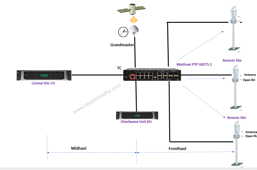
Option LLS-C3 and LLS-C2 are gaining more prominence. In LLS-C3 SyncE and PTP are sourced from Telecom boundary clock as depicted in the below picture.


Here are the options for clock spread /distribution.
Segregate transport for User/Control and the synchronization, this means a dedicated transport network for synchronization. In the below diagram Fiber-1 carries the S-Plane (Synchronization Plane) and Fiber-2 carries the C-Plane (Control Plane) and U-Plane (User Plane). This design will free PTP from any packet congestion in network. This is still cost effective as a single optical cable has many fibers between 12-144, where 1 fiber from the bundle can be assigned for Sync plane to maintain the KPI’s.

Implementing GNSS at all cell sites , a clock directly from heaven to node is a simpler approach. Synchronization signals are delivered from GNSS directly to nodes. Servers are now available with adapters with built in GNSS modules. However GNSS has some limitations like receiver costs, line-of-sight limitations and security threats like jamming or spoofing .

The third option is to carry synchronization in-band over a transport network

IEEE1588 Precision Time Protocol (PTP) and Synchronous Ethernet (SyncE) are the two protocols which takes care of time synchronization.
Most of the documents depicts PTP and/or SyncE usage in ORAN. Are these two protocols rivals? I believe the answer is NO and I think they are complementing each other. In fact, networks adopt a hybrid model whereby SyncE assists PTP, SyncE adds physical-layer clock distribution and synchronization to Ethernet
SyncE takes care of syntonization, enabling frequency distribution in Ethernet networks over the physical Ethernet layer. SyncE has greater level of accuracy than carrying frequency at the packet level because it can’t be affected by packet delay variation. SyncE clock operates on physical layer of OSI and management of the SyncE uses special layer-2 protocol frame: ESMC (Ethernet Synchronization Message Channel).SyncE is is a logical communication channel. It transmits Synchronization Status Message (SSM) information, which is the quality level of the transmitting synchronous Ethernet equipment clock (EEC), by using ESMC protocol data units (PDUs).
PTP is typically used only for phase synchronization in conjunction with SyncE for frequency synchronization, It works at layer 3 using UDP port 319,320 as its transport protocol and Ether type 0x88F7 on layer-2. There are 2 PTP Telecom Profiles for Time and Phase. G.8275.1 (Full Timing Support) and G.8275.2 (Partial Timing Support).

Multicast clock propagation example is shown in the below diagram. Design can have many variations based on the vendor features, network design,
| G.8275.1 | G.8275.2 |
| Operates directly over Ethernet using multicast messaging | Operates using unicast delivery over IPv4 or IPv6 networks |
| Requires a BC or TC at every node in the network, with physical layer frequency support (e.g. SyncE) | Operates over existing telecoms networks, with no PTP “on-path” support required |
| Message rate 16 messages per second | Message rates up to 128 messages per second |
For 5G networks which is predominantly based on Time Division Duplex (TDD), G.8275.1 is the recommended profile to be used, but requires that all switching nodes in the network can operate as PTP Telecom Boundary Clocks (T-BCs).
On layer-3 PTP message is conventionally carried as UDP payload.

White Rabbit is the name of project which has developed ethernet based network to provide sub-nanosecond synchronization accuracy .White Rabbit implementation White Rabbit (WR) is a protocol which extends the Precision Time Protocol (PTP) to provide synchronization of sub-nanosecond, sub-50 picoseconds precision, and can cover distances of tens of kilometers in a topology. Here are the components of White rabbit

PTP alone is not enough for good clock accuracy due to its packet network propagation and time stamps are needed granular and precise.
With the SyncE, phase shift can be measured from the transmitted clock on master and receiving it on Master (loop feedback) . PLL in the slave follows phase changes reported by master.
White Rabbit synchronization defined under the form of a Profile of the Precision Time Protocol (IEEE 1588) also referred as referred to as WR PTP.
PTP synchronization is implementation-dependent based on the packet network attributes, design and has limitations like link asymmetry, PTP message exchanges which is subjected to PTP syntonization and precision and resolution of time stamps.
The clock is encoded in the Ethernet carrier and recovered by the PLL of the PHY. PTP synchronizes the local clocks with the master clock by measuring and compensating the delays introduced by the link.

On high level ,Field Programmable Gate Arrays (FPGA) implements Ethernet and low-level timing functions of PLL, DMTDs and fine timestamping and PTP manages PTP stack. PLL at receiver recreates the clock ,it will keep wander and jitter in check.Wander is the clock timing variance below 10Hz and the jitter is above 10Hz. Digital Dual Mixer Time Difference handles the phase.
Let us now focus on the slave part, typically CU/RU which is the consumer of synchronized clock. In fact it is a NIC , Network card interface.
I started working on Openstack and VNF instantization from 2016 with the LTE/MME/MCC VNF’s onboarding. Since then most of my projects were COTS based applications in the form of telecom VNF. Industry standards servers are now more fined tuned with the virtualized functions. In the context of clock synchronization, I will cover the relevant portion available on COTS today. With the advent of virtualization” software based network functions are run on the x86 based Industry standard servers.
With VRAN/ORAN , BBU runs as VNF / Container on the standards COTS server.
Openran is dis-aggregation of hardware and software freeing from vendor lockins. In the diagram below CU , DU, RIC controllers and off course BBU components runs the modular software stack with open North and South bound interfaces. In ORAN architecture most of the applications run as container or as a Virtual machine predominantly on Red hat platform like Openshift, Openstack and RHEL .

Intel Ethernet 800 Series like E810-XXVDA4T and Marvel RAN accelerator supports High-precision timing synchronization with IEEE 1588 PTP, SyncE and a GNSS provision on the card.


Marvell Technology with Dell have come up with the solution called inline layer-1 accelerator. In Open RAN split 7.2 architecture, layer 1 (lower and upper) is split , the RU process lower layer and DU process upper layer. This layer-1 process is offloaded to ran accelerator card which also enable timing requirements with precision time protocol (PTP) and Synchronous Ethernet (SyncE)


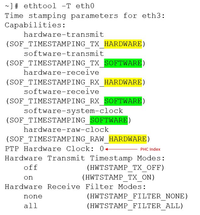
The PTP reaches the NIC on the server then Kernel and Linux operating system aligns the clock it received from the boundary clock. With hardware PTP support, the NIC has its own on-board clock, which is used to time stamp the received and transmitted PTP messages. It is this on-board clock that is synchronized to the PTP master, and the server’s system clock is synchronized to the PTP hardware clock on the NIC.
The module ptp4l implements Boundary and Ordinary clock, phc2sys synchronizes the system clock to hardware clock and pmc handles management of ptp

We can check Driver and Hardware Support with eth tool
In next episode we will delve into the templates for Openstack and OpenShift deployment. For any feedback you can write me on telecomighty@gmail.com